Arduino Week 1 - LEDs and Basic Input
Introducing the Arduino and Experimenting with LEDs!
Introduction...
Physical computing involves the building of interactive physical systems through the combination of software and hardware that can sense, repond, and interact with the environment.It is a very broad topic that can encompasses industrial systems such as smart traffic controls and automated factory systems. However, it is more commonly associated with the artistic realm and DIY hobby projects. Arduino’s are a great way to get involved with physical computing, and to experiment with the interaction between hardware and software.The arduino itself is an open source platform that can be used for the building of electronic projects. It is made up of a programmable circuit board and the IDE (Integrated Development Environment) that is used to write and upload software to the board. The Arduino language is a simplified version of C++. The board I will be using throughout my experimentations with arduino and with physical computing as a whole is the Arduino Leonardo. The Leonardo board features 32kb of flash memory, 2.5kb of SRAM, and a clock speed of 16MHz.
Components Needed...
- Arduino.
- Breadboard.
- Jumper Wires.
- 2 x LED.
- 2 x 100 Ohm Resistor.
Basic LED Blink...
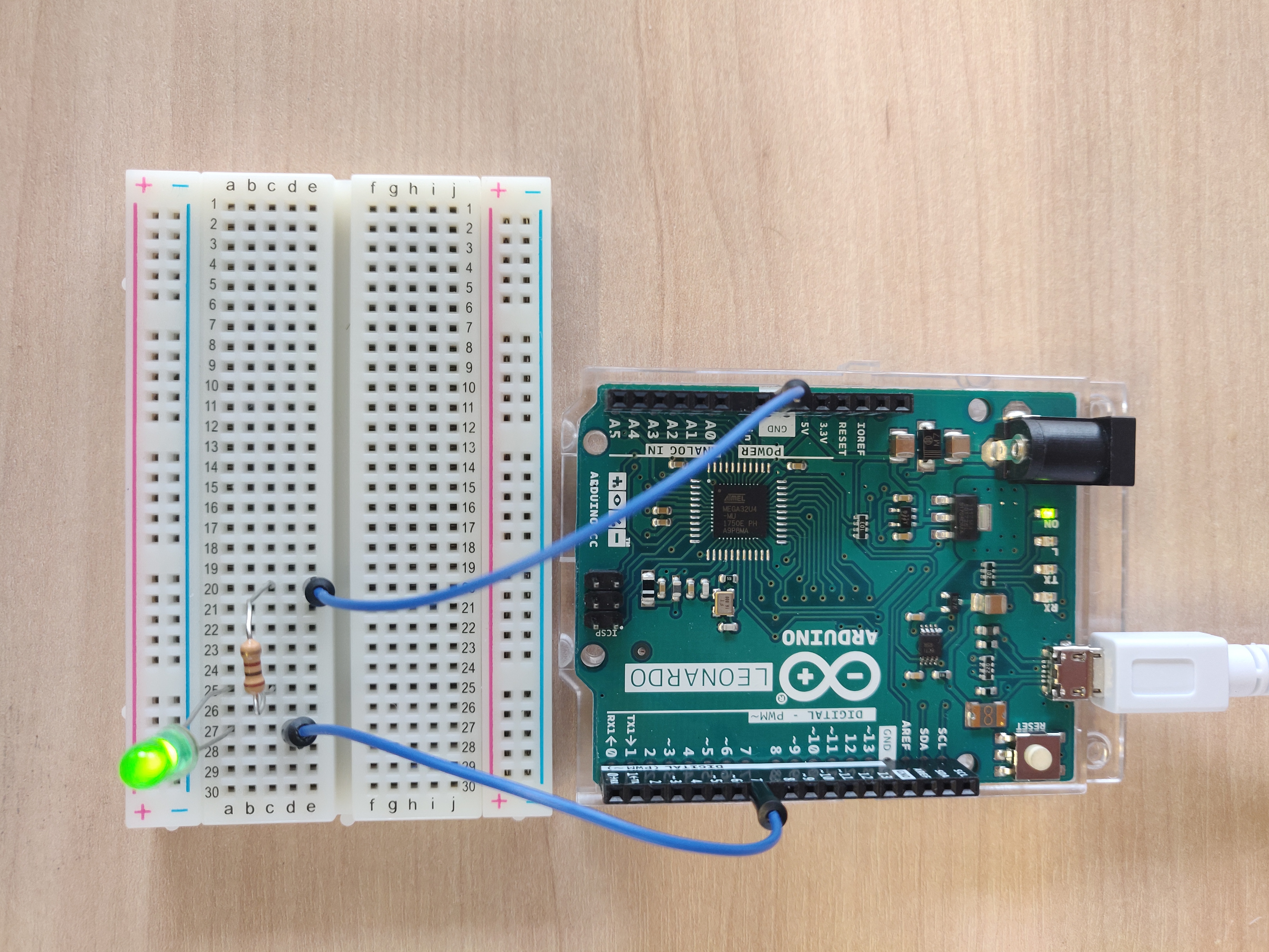
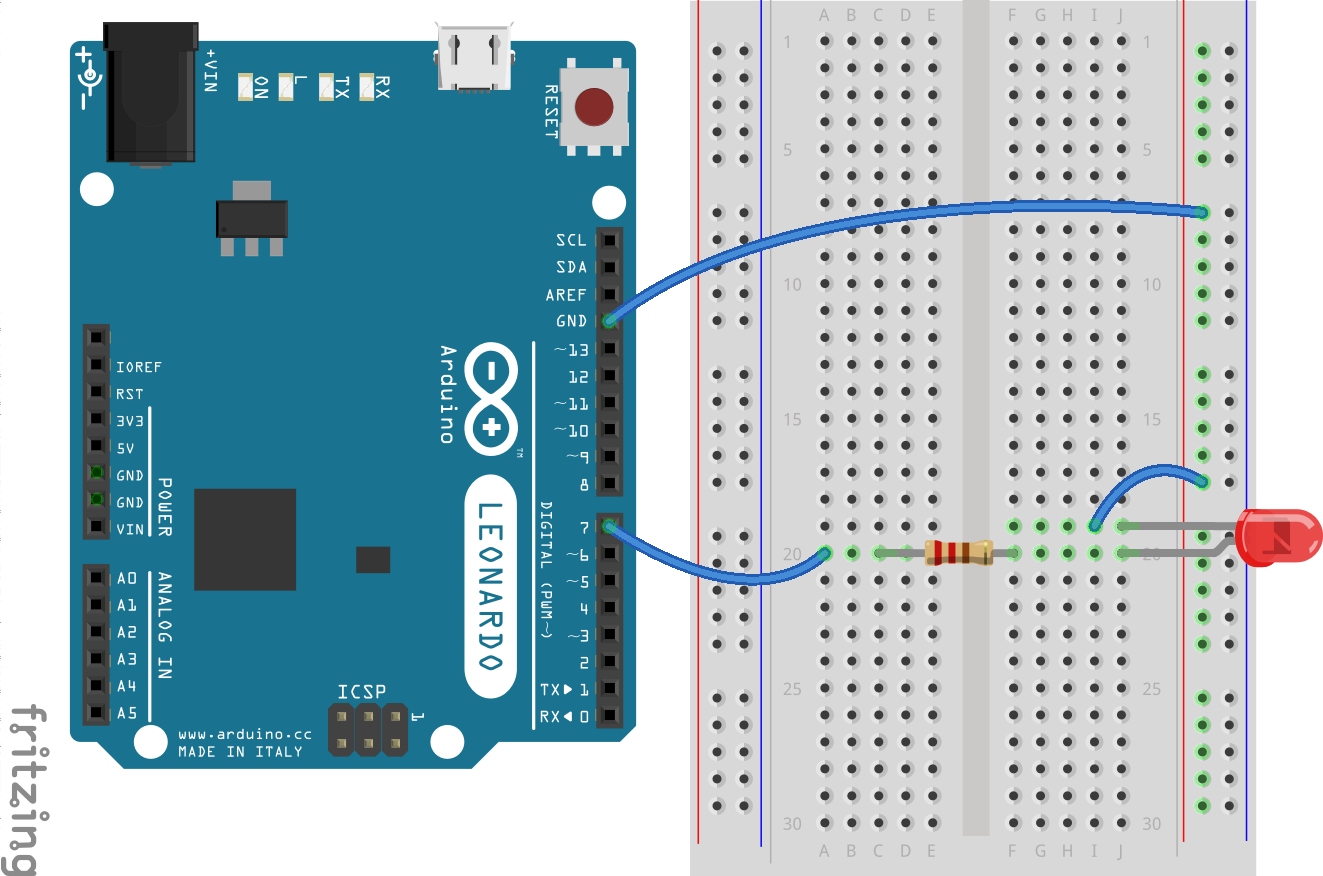
To get started experimenting with the Arduino, I employed the use of the blink tutorial on the Arduino website and attempted to recreate it as best as possible (Arduino.cc, 2015). The circuit itself was set up as shown in the schematic below. One jumper wire was connected from output pin 7 to the breadboard. The anode of the LED was then connected to the output pin, and the cathode was connected to the resistor. The anode and cathode can be differentiated on an LED by the length of the pins. The longer pin on the LED is the anode or the positive pin, with the shorter pin bring the cathode or negative pin. The polarity of the LED is important as it determines what command we use in the IDE to turn the LED on and off. If we connect the anode to the output pin, we can turn the LED on by writing the value ‘HIGH’ to it, whereas if we connect the cathode to the output pin we would turn it on by writing ‘LOW’ to it.
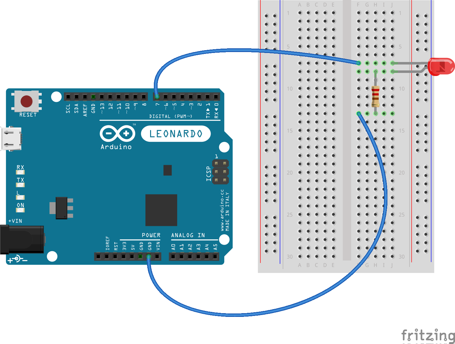
In regards to the code, the Arduino IDE makes it very easy to create simple I/O programs. For this example, I simply set the variable for the output pin, which in this case is 7. We define this variable outside the ‘setup()’ and ‘loop()’ functions in order for it to be a global variable, meaning that all functions can use it. Then we declare which pin we are using with this variable in the ‘setup()’ function, and state whether it is an input or an output, with the function ‘pinMode()’. Finally, in the ‘loop()’ function, we use the ‘digitalWrite()’ function to write the value of ‘HIGH’ to our output pin, which has the visible effect of turning the LED on. Next we delay the program for one second and then write the value of ‘LOW’ to our output pin, which turns the LED off. The program is then delayed for another second and looped!
                        // Setting Global variable for output pin.
                        const int OUTPUT_PIN = 7;

                        void setup() {
                            // Declaring the output pin with the global variable as defined above.
                            pinMode(OUTPUT_PIN, OUTPUT);
                        }

                        void loop() {
                            // Writing the value of HIGH to the output pin 7. (HIGH = ON).
                                digitalWrite(OUTPUT_PIN, HIGH);
                            // Delaying the program for one second to control the speed of the blink. (1000 milliseconds).
                                delay(1000);
                            // Writing the value of LOW to the output pin 7. (LOW = OFF).
                            digitalWrite(OUTPUT_PIN, LOW);
                            // Delaying the program again for one second.
                            delay(1000);
                        }
Multiple Blinking LEDs...
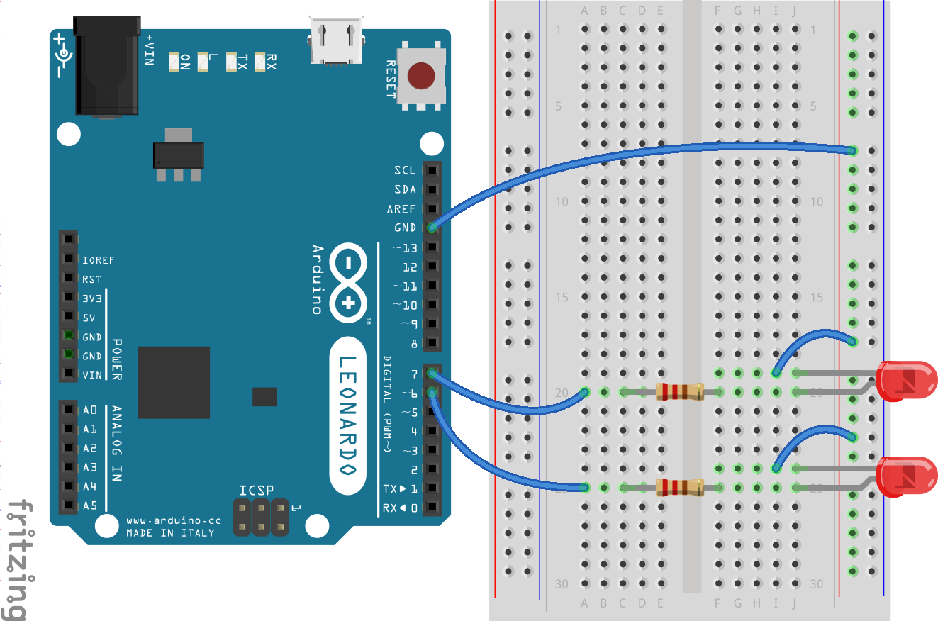
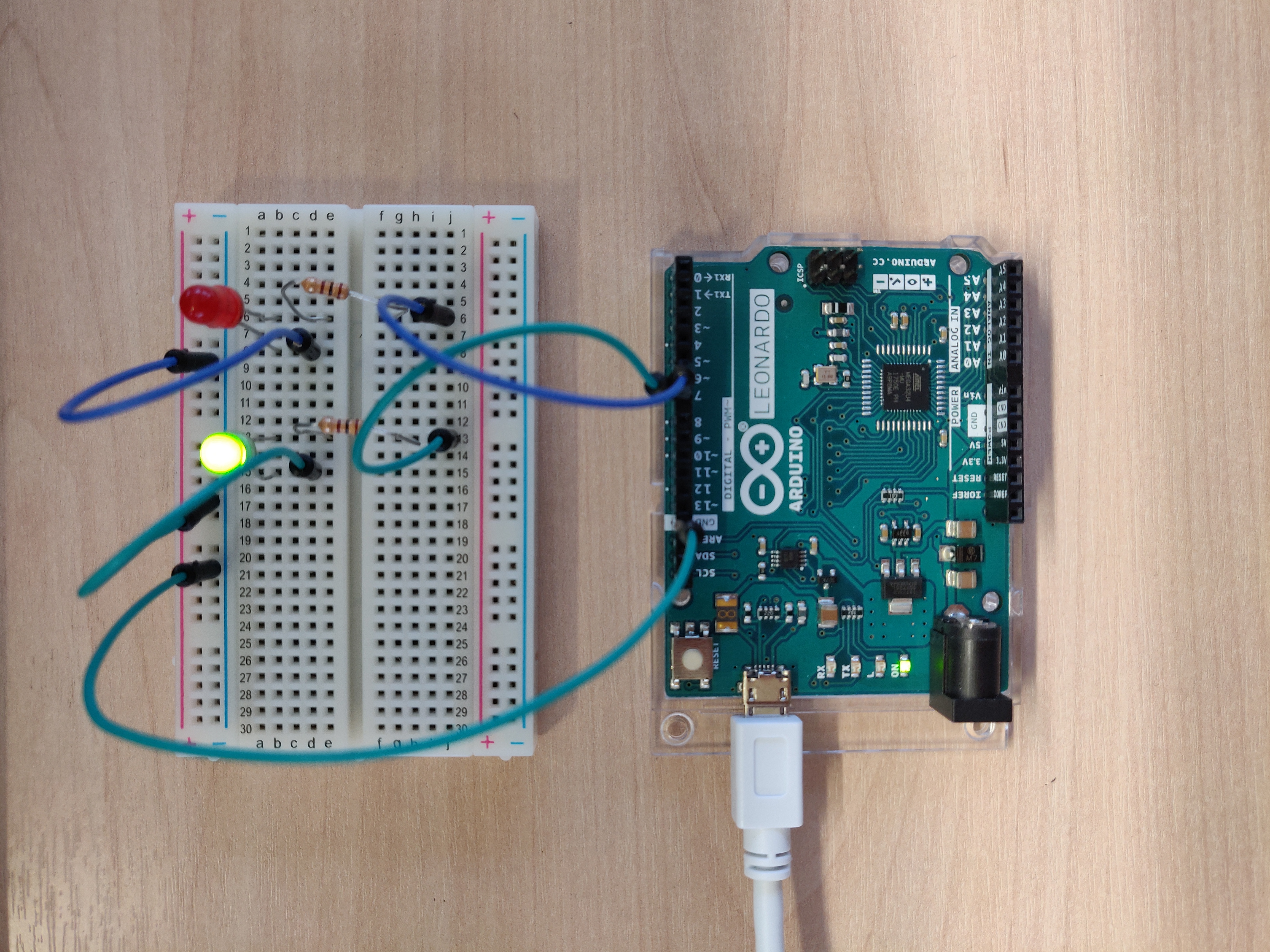
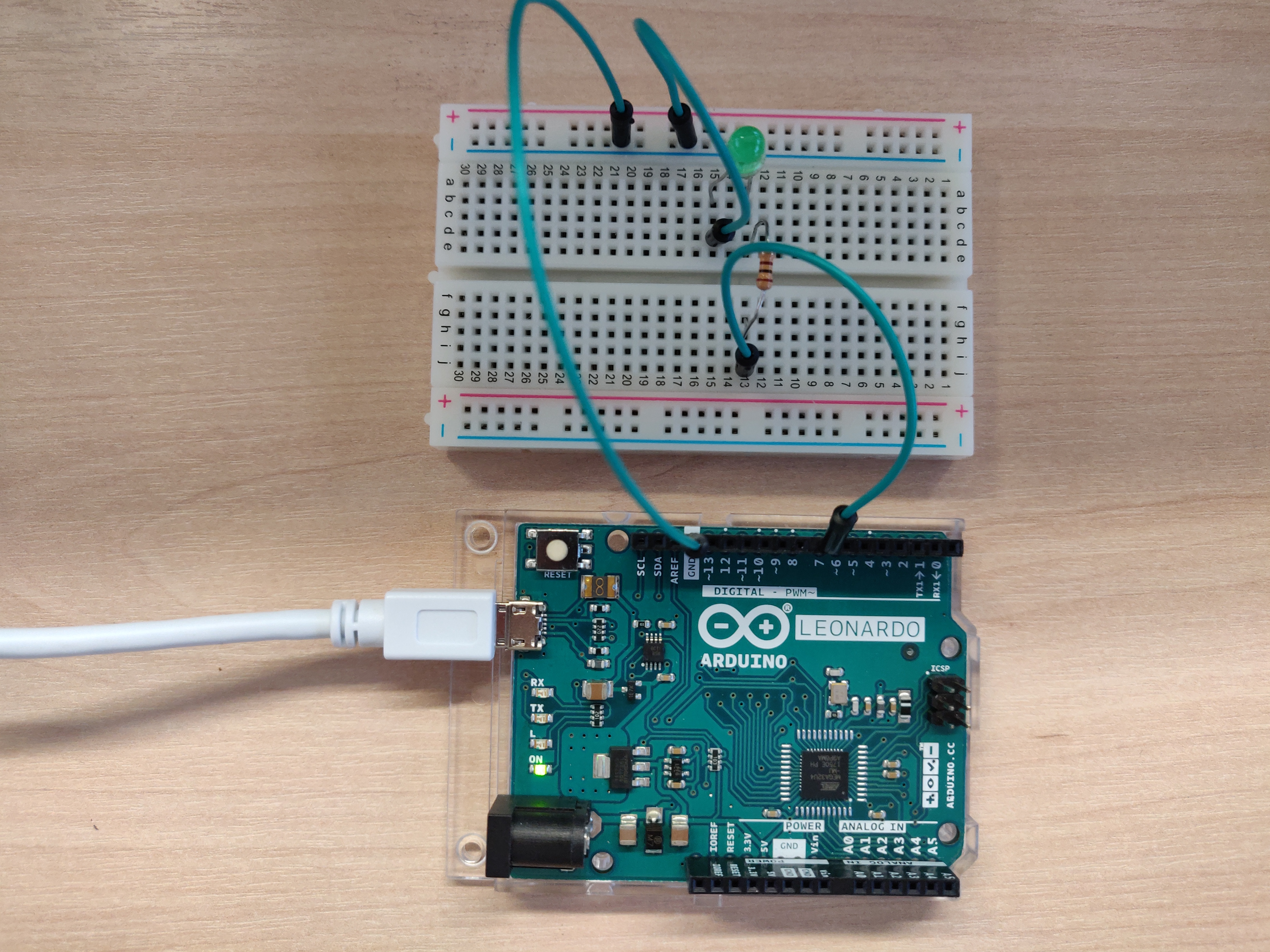
To further extend this experimentation, I decided to add another LED into the circuit to see whether I could get two blinking alternately. I used the same equipment as above, with the exception of an extra LED, two 1k OHM resistors (as they were the only multiples I had), and some extra cables. In regards to the code, much of it was the same. The only changes I made were adding another output pin (6 in this case), declaring this output, and then writing opposite values to this new output to alternate it from the original output pin 7. This had meant that one LED would be on while the other was off, creating quite a nice flashing effect!
                        // Setting Global variables for output pins.
                        const int OUTPUT_PIN_1 = 7, OUTPUT_PIN_2 = 6;

                        void setup() {
                            // Declaring the output pins with the global variables as defined above.
                            pinMode(OUTPUT_PIN_1, OUTPUT);
                            pinMode(OUTPUT_PIN_2, OUTPUT);
                        }

                        void loop() {
                            // Writing the value of HIGH to the output pin 7. (HIGH = ON).
                            digitalWrite(OUTPUT_PIN_1, HIGH);
                            // Writing the value of LOW to the output pin 6. (LOW = OFF).
                            digitalWrite(OUTPUT_PIN_2, LOW);
                            // Delaying the program for one second to control the speed of the blink. (1000 milliseconds).
                            delay(1000);
                            // Writing the value of LOW to the output pin 7.
                            digitalWrite(OUTPUT_PIN_1, LOW);
                            // Writing the value of HIGH to the output pin 6.
                            digitalWrite(OUTPUT_PIN_2, HIGH);
                            // Delaying the program again for one second.
                            delay(1000);
                        }
Controlling LED with Basic Input...
The final challenge I set myself for this introductory session was to see if I could control an LED with basic input using the serial monitor. The arduino serial monitor acts as a separate terminal for the Arduino board itself and can communicate with the boards by sending and receiving serial data. In our case, this serial data is simply sent over the micro USB that is plugged into the Arduino from the computer we are developing on.
I used the exact same circuit layout as the second blinking experiment, except I removed one of the LEDs, simply for ease of use. In terms of the code, we first set the variables for the output pin, the ‘incomingByte’ so we can check for and read incoming data, and a boolean for the ledState so we can alternate the value of the output pin. In the setup loop we initialise serial communication for the function ‘Serial.begin(9600)’ and declare the output pin as with the other examples. In the loop function, we first check to see if there is incoming serial data, and if there is, we check to see if this data is a ‘1’ or a ‘0’. If the data is a ‘1’, then the ‘ledState’ boolean will be set to true, and if it is a ‘0’, it will be set to false. Finally, we write the value of ‘ledState’ to the output pin, in this case it is 7. If the value of ‘ledState’ is true, the LED on pin 7 will be turned on, if it is false, the LED will be turned off!
                        // Setting global variable for output pin.
                        const int OUTPUT_PIN = 7;
                        // Setting varibale to read incoming serial data.
                        byte incomingByte;
                        // Setting boolean for the state of the LED.
                        boolean ledState = false;

                        void setup() {
                            // Initialise serial communication.
                            Serial.begin(9600);
                            // Declaring output pin with the variable as defined above.
                            pinMode(OUTPUT_PIN, OUTPUT);
                        }

                        void loop() {
                            // Check to see if there is incoming serial data.
                            if (Serial.available() > 0) {
                                // Read the oldest byte in the serial buffer.
                                incomingByte = Serial.read();
                                // If the incoming byte is a 1, turn on the LED.
                                if (incomingByte == '1') {
                                  ledState = HIGH;
                                }
                                // If incoming byte is equal
                                if (incomingByte == '0') {
                                  ledState = LOW;
                                }
                            }
                            // Writing to the output pin with the value of ledState.
                            // If value is true, the LED will be turned on, else it will turn off.
                            digitalWrite(OUTPUT_PIN, ledState)
                        }
Conclusion...
With these exercises I feel as though I gained I good understanding of the basic Arduino functions and how the IDE communicates with the board itself. I was also able to refresh my knowledge on how basic electronic components and circuits work - something which I have not looked at in a number of years! I have also begun to see the potential of the Arduino - a board which seems so simple can control a wide range of different components easily and effectively. I am excited to work more with the Arduino and experiment further to see what I can create!
References...
Arduino.cc. (2015). Arduino - Blink. [online] Available at: https://www.arduino.cc/en/Tutorial/Blink [Accessed 13 March 2019].