Arduino Week 2 - RGB LEDs
Introducing RGB LEDs - how they work and how to use them!
Introduction...
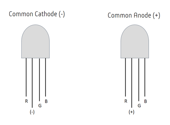
Quite simply, RGB LEDs are just three LEDs packaged into one. There is one red LED, one green LED, and one blue LED. You are able to choose the intensity of each colour and this is how you can alter the colour of the LED and produce almost any colour. RGB LEDs have four pins, one for sending input to each of the colours and then one for power (cathode or anode). There are two types of RGB LEDs available for consumers to buy; common cathode (-) type and common anode (+). According to Rio Santos (2019), the difference between these two types is that in a 'common cathode RGB LED, all three LEDs share a negative connection (cathode). In a common anode RGB LED, the three LEDs share a positive connection (anode)'. The different pins can be identified if you oriientate the component so that the longest leg is the second from the left. The order should then be from left to right; red pin, anode/cathode, green pin, blue pin.
Components Needed...
- Arduino.
- Breadboard.
- Jumper Wires.
- RGB LED.
- 3 x 220 Ohm Resistor.
Turning on the RGB LED and Controlling Colour...
The first logical step for this experiment would be to actually get the LED on and then learn how to alter the colour of the LED! Controlling the colour of the LED is slightly more complicated than just sending varying values to each one of the pins, although this description isn't dissimilar to what is occurring. The technique used is called Pulse Width Modulation (PWM). PWM is a technique that allows the amount of power that is delivered to a component to be controlled accurately and efficiently (Teja, 2018). Not only can this technique be used to control the brightness/intensity of an LED, it also has applications within motor and servo control.
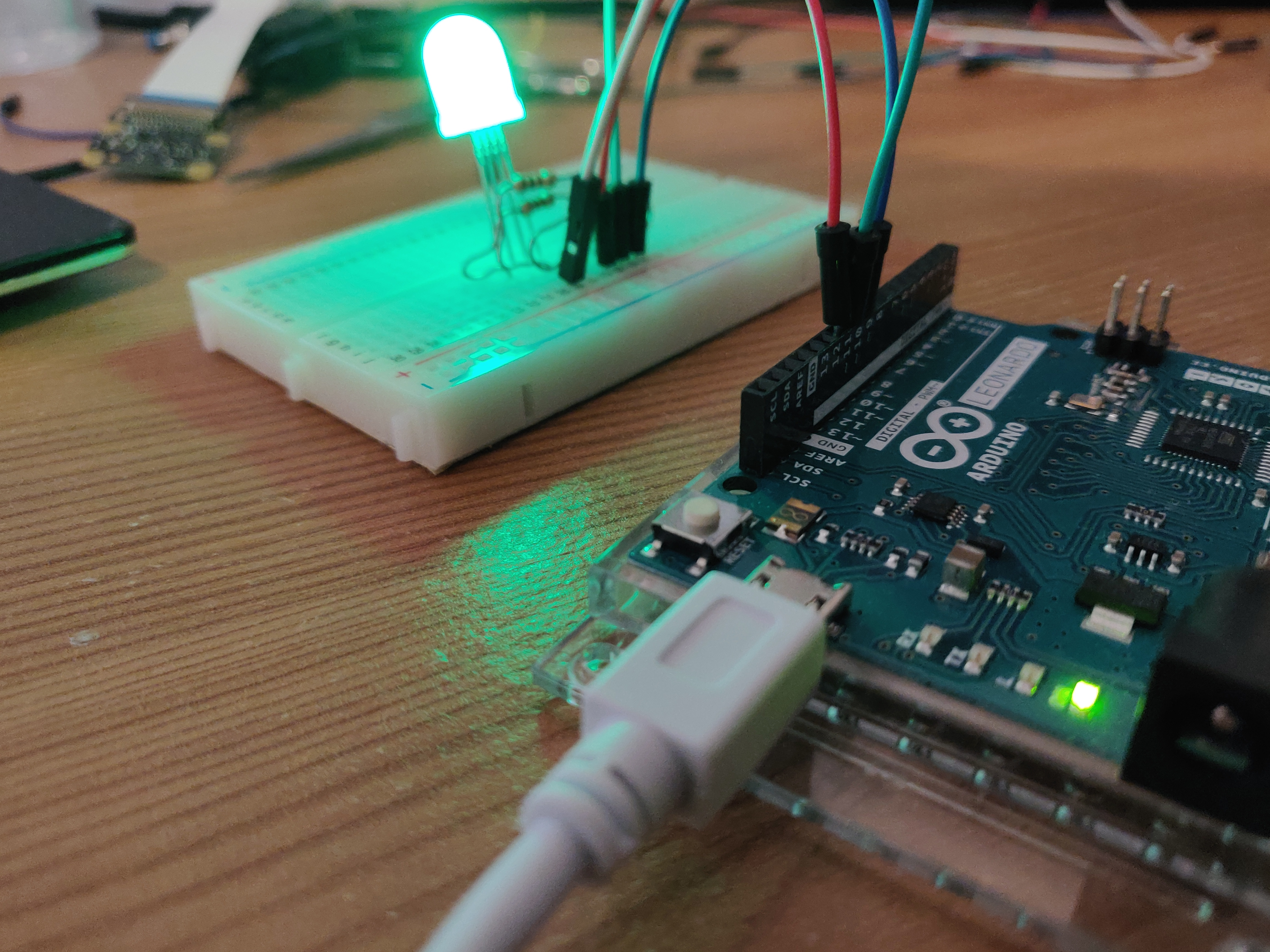
As mentioned above, the first step we should take is to just turn the LED on. The connection of the RGB LED to the breadboard and Arduino is relatively easy. First plug the LED into the breadboard so the cathode/anode pin is second from the left, this will reduce confusion in identifying the pins later on. Next, plug resistors into the board so one leg is attached to once of the LEDs colour pins (1, 3, or 4), and the other leg so that it has a vertical rail of its own to prevent crossover. Jumper wires are then used to attach the free end of each of the resistors to their own pin on the Arduino. I have used pins 9, 10, and 11 for the purposes of this experiment. The reason for doing this is these are the pins on the Leonardo that support PWM. If you are using a different board, double check the documentation to see if they are the same, if they aren't then you will need to change this otherwise the code below will not work! The final connection to make depends if you have an anode or cathode type LED. If you are using common cathode RGB LED, the jumper wire should connect from the GND on the Arduino to the second pin of the LED, if you are using common anode type, then the lead will go from the 5v on the Arduino to the second pin of the LED.
For the code, we specify which pins we are using and assign a variable to them. In this case I am using pins 9, 10, and 11. We then set the mode for each of these pins in the setup function which is of course output. Then in the loop function we use the 'analogWrite()' function to specify which pin we are using and the intensity of the colour. Again, there are some changes whether you are using anode or cathode type LED. If the LED is anode, then '0' would be the highest intensity and '255' would turn that particular colour off. The opposite is true for type cathode! The code below should cycle through red, green, and blue respecitvely.
                        // Set the numbers for the pins.
                        int redPin = 9;
                        int greenPin = 10;
                        int bluePin = 11;

                        // Setup the pins with the variables about and state they are output.
                        void setup() {
                          pinMode(redPin, OUTPUT);
                          pinMode(greenPin, OUTPUT);
                          pinMode(bluePin, OUTPUT);

                        }

                        // State the intensity of each pin and cycle through each colour respectively.
                        void loop() {
                          analogWrite(redPin, 1);
                          analogWrite(greenPin, 255);
                          analogWrite(bluePin, 255);
                          delay(2000);
                          analogWrite(redPin, 255);
                          analogWrite(greenPin, 1);
                          analogWrite(bluePin, 255);
                          delay(2000);
                          analogWrite(redPin, 255);
                          analogWrite(greenPin, 255);
                          analogWrite(bluePin, 1);
                        }
Smoothly Transitioning through Colours...
The next step I wanted to take was to cycle smoothly through the RGB LED colours to create an ambient effect. I really struggled with this task and made some progress using some nested for loops and if/else statements but I simply couldn't get it to work smoothly or transition through the colours in sequence. As a result I had to take to the internet and followed a tutorial by a user named 'Zimmermann ARD' (2017). The code used is extremely efficient and achieves the aim in a matter of lines. It was by far the most efficient implementation I found after watching numerous tutorials and looking through other snippets of code!
The circuit itself is exactly the same as the previous experiment however the code is quite dramatically changed. We still initialise the integers for the pins at the start of the sketch, however we then specify values for 'r', 'g', and 'b'. We set 'r' to '255' and leave the other two at '0'. This will be our initial value to use as a starting point in the loops. The next step is to implement three for loops which use these values as input and compare them to one another, cycling through each iteration smoothly. The first for loop cycles through combinations of red and blue, the second through combinations of blue and green, and the third through red and green; covering all possible combinations!
                        // Sketch completed following tutorial by zimmermannard.
                        // Set numbers for the pins.
                        int redPin = 9;
                        int greenPin = 10;
                        int bluePin = 11;

                        // Set initial values for colours.
                        int r = 255;
                        int b;
                        int g;

                        // Setup function left empty.
                        void setup() {

                        }

                        // Loop function with for loops to iterate through each combination of colours.
                        void loop() {

                          for (; r>=0, b<255; b++, r--) {
                            analogWrite(redPin, r);
                            analogWrite(bluePin, b);
                            delay(200);
                          }

                          for (; b>=0, g<255; g++, b--) {
                            analogWrite(bluePin, b);
                            analogWrite(greenPin, g);
                            delay(200);
                          }

                          for (; g>=0, r<255; r++, g--) {
                            analogWrite(redPin, r);
                            analogWrite(greenPin, g);
                            delay(200);
                          }

                        }
Conclusion...
This concludes the experiments I conducted on RGB LEDs. This component could have many practical components as a display for sensors, art, or simply just a nice ambient light! This is definitely something I would like to experiment with further and is a potential component to be used within my final project!
References...
Santos, R. (2019). How do RGB LEDs work? | Random Nerd Tutorials. [online] Random Nerd Tutorials. Available at: https://randomnerdtutorials.com/electronics-basics-how-do-rgb-leds-work/ [Accessed 20 March 2019].
Teja, R. (2018). RGB LED with Arduino - Driving an RGB LED using Arduino. [online] Electronics Hub. Available at: https://www.electronicshub.org/rgb-led-with-arduino/ [Accessed 20 March 2019].
Zimmerman. (2017). RGB LED Smooth Color Transition Using Arduino UNO. [online] Available at: https://www.instructables.com/id/RGB-LED-Smooth-Color-Transition-Using-Arduino-UNO/ [Accessed 21 March 2019].