Arduino Week 5 - DC Gear Motor
Introducing the Gear Motor with Simple Interaction!
Introduction...
This week we were free to experiment with our choice from a variety of different components. Following on from the experiment I completed using the servo, and the theme of remote controlled vehicles, I decided to experiment with a DC motor. This was on of the more exciting components to me as it is very easy to see their applications, and actively witnessing the code you have written moving a component is always fun!
Components Needed...
- Arduino.
- Breadboard.
- Jumper Wires.
- 1 x DC Motor.
- 1 x Transistor.
- 1 x Diode.
- 1 x 270 Ohm Resistor.
Basic Motor Blink...
I started with a very simple experiment and decided to just work out how to make the motor turn intermittently, or blink. This idea was not dissimilar to the first experiment with making the LED blink; it allows us to gain a deeper understanding of what is actually going on with the circuit and then move forward to more complex circuits. In order to accomplish this, a couple of new components needed to be introduced; a transistor and a diode. Transistors are semiconductor devices that are used to amplify or switch electronic signals and electrical power whereas a diode is a device that allows the flow of current in one direction only.
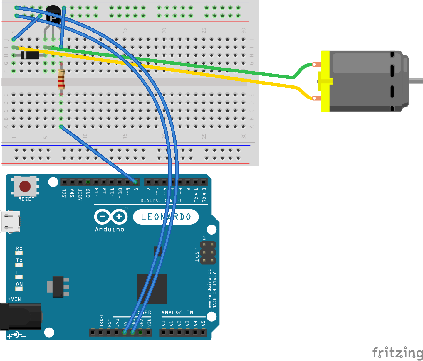
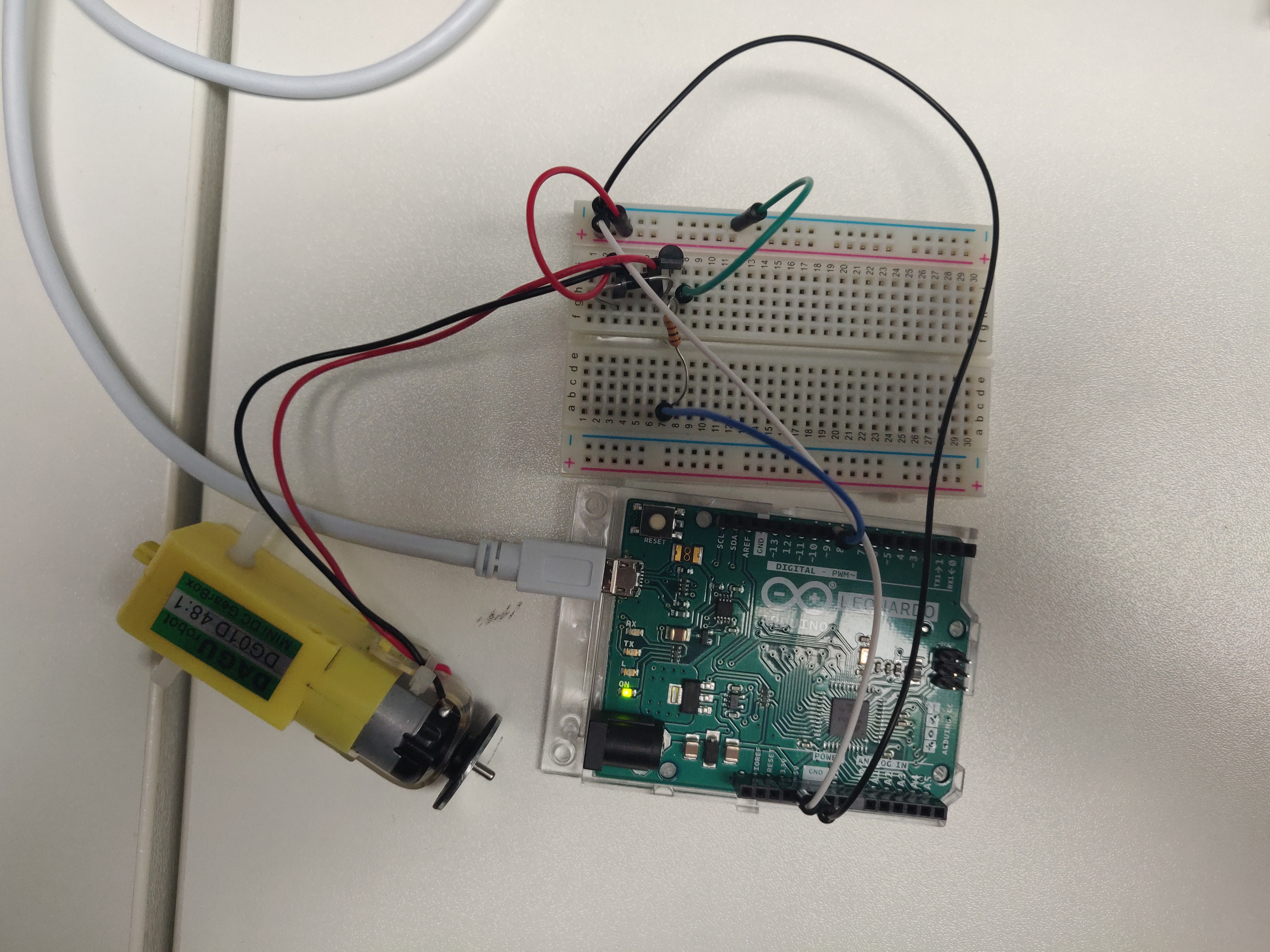
The circuit itself was relatively simple, however it took a number of attempts to get the diode in the correct position with the correct orientation. Unbeknownst to me when putting the circuit together initially, it is very important which way the diode is placed in the circuit. On the majority of diodes there will be a silver band on one end, indicating which direction it is allowing the current to flow in. Apart from the introduction of these new components, the rest of the circuit was standard; jumper wires connecting the ground and 5v pins on the arduino to the breadboard, as well as pin 9 from the arduino to the breadboard in order to add an element of control. In regards to the code, it was also fairly simple; the output pin 9 was specified then a value of ‘HIGH’ was written to it, the code delayed for five seconds, then a value of ‘LOW’ was set to the pin, and another delay of five seconds was specified. This was it! This had the effect of the motor turning on for five seconds and then off for another five seconds, effectively making the motor blink.
                        // Setting Global variable for output pin.
                        const int OUTPUT_PIN = 7;

                        void setup() {
                            // Declaring the output pin with the global variable as defined above.
                            pinMode(OUTPUT_PIN, OUTPUT);
                        }

                        void loop() {
                            // Writing the value of HIGH to the output pin 7. (HIGH = ON).
                                digitalWrite(OUTPUT_PIN, HIGH);
                            // Delaying the program for one second to control the speed of the blink. (1000 milliseconds).
                                delay(1000);
                            // Writing the value of LOW to the output pin 7. (LOW = OFF).
                            digitalWrite(OUTPUT_PIN, LOW);
                            // Delaying the program again for one second.
                            delay(1000);
                        }
Conclusion...
The experiment I completed with DC motors, along with the stepper motor experiment, was a great step up from the previous experiments I had been doing which mainly centred around LED input and output. It allowed me to visualise the possibilities of what can be achieved with arduino’s and physical computing in general in greater detail. Much like with the servo, I would be keen to see whether I could get the motors working wirelessly; being able to control them from a remote machine or even with a controller!