Arduino Week 3 - Introduction to Light Dependent Resistors (LDRs).
Introducing LDRs and how they can be used to Control other Components!
Introduction...
The aim in my third session of experimenting with the Arduino and simple electronic components was to employ the use of light dependent resistors (LDRs) and to ascertain how they can be used to work out the resistance, and also how they can be used to control LEDs. An LDR is a component that has a variable resistance that is changed based on the intensity of the light that it receives (Mirza, 2019). In the majority of cases, the resistance that an LDR provides falls as the intensity of the light increases. LDRs have a wide range of different applications, the most common of these being as a lighting switch and for camera shutter control. In regards to their applications as a lighting switch, they can be used to automatically turn on a light when the level of light gets to a certain level, for example, street lights that turn on when it begins to get dark. In regards to camera shutters, they can be used to control the shutter speed on a camera; the shutter speed will be adjusted and set to the appropriate level based on the intensity of light in the surrounding environment.
Components Needed...
- Arduino.
- Breadboard.
- Jumper Wires.
- 1 x LDR.
- 1 x 1k Ohm Resistor.
Getting Output from LDR...
The first challenge was to determine some kind of legible output from the LDR by using a potential divider circuit. A potential divider, or voltage divider, circuit is a circuit that produces an output voltage that is a fraction of its input voltage. In this instance, we would be using two resistors connected in a series, the first being the LDR (which we don’t know resistance of) and the second being a resistor which we know the value of, to make the calculations easier.
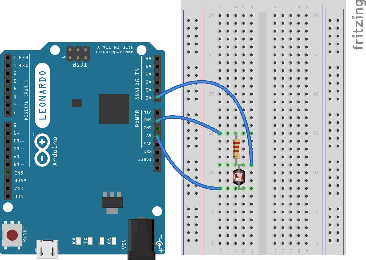
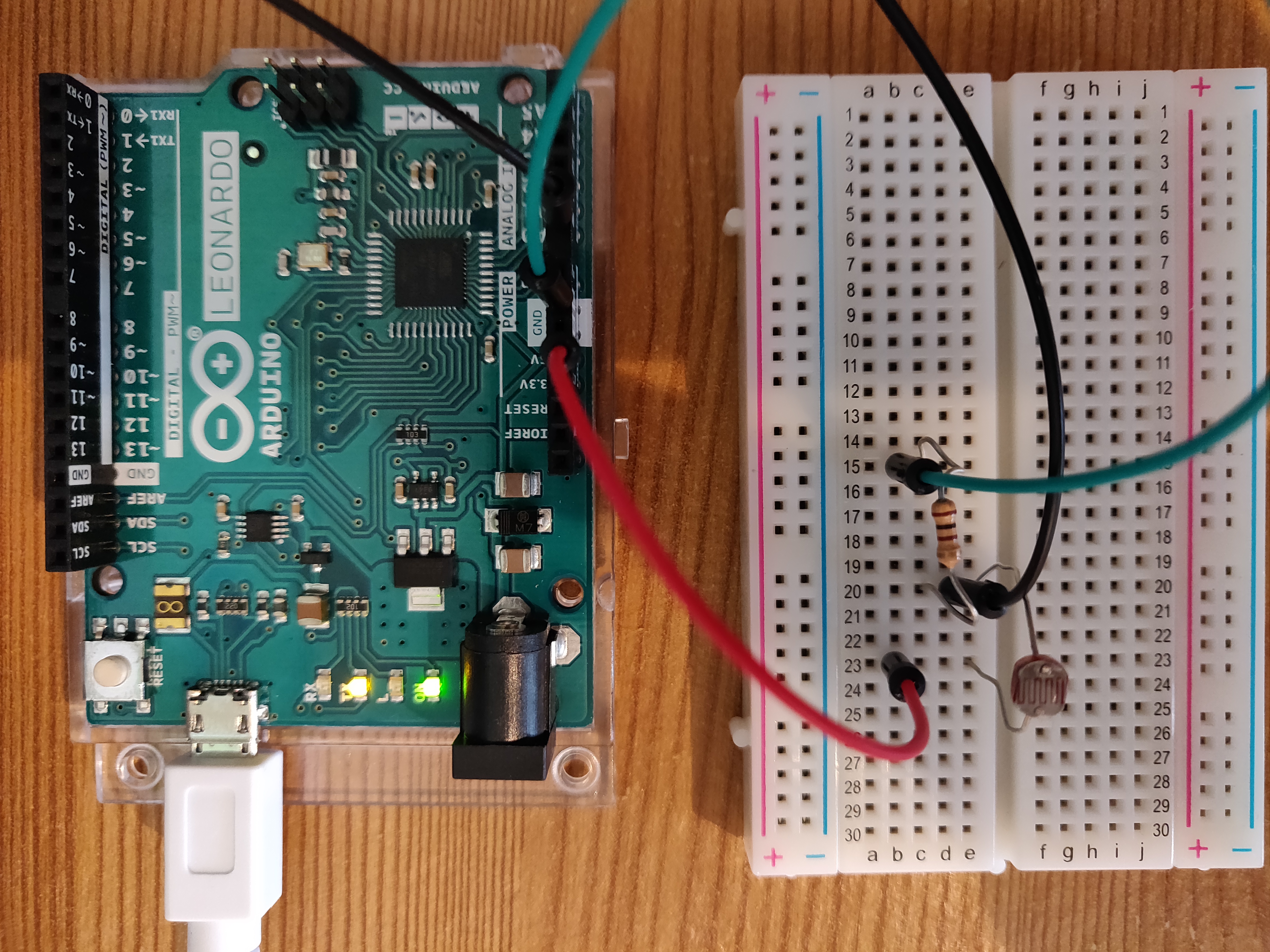
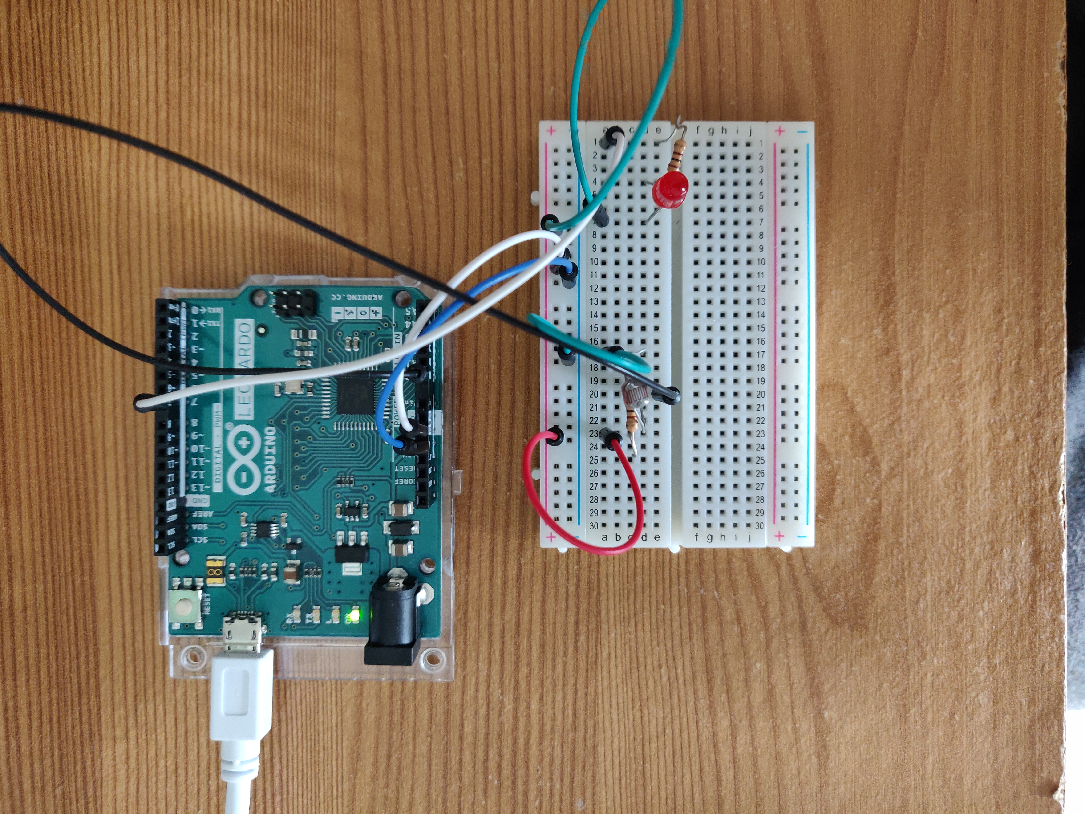
The circuit was set up as shown below; one lead was connected from the 5v output on the Arduino to the LDR, the 1k OHM resistor was then placed on the same leg of the LDR and the other end was connected to the ground pin on the Arduino via a jump lead. Finally, another jump lead was connected from the A0 (analog in) pin on the Arduino to the intersection of the LDR and the fixed resistor. In terms of the code, I loaded up the ‘AnalogReadSerial’ example from the basic section of the examples. This example takes the output from the LDR, converts it into serial data and then displays it to the serial number. In the room I was in at the time (an artificially lit room in early evening), I was receiving values of 0-360 on the serial monitor, the higher values representing a higher light intensity. From these values, I was able to work out the voltage across the LDR. I converted this value by dividing it by 1024 and multiplying it by 5 (for the original voltage as supplied by the Arduino). This left me with a value of around 1.80v in the standard lighting conditions I was in.
                        // Defining LDRpin and the initial output value of the LDR.
                        #define LDRpin A0

                        int LDRValue = 0;

                        // Setting serial port for communication from board to computer.
                        void setup() {
                            Serial.begin(9600);
                        }

                        // Reading value from LDR, printing it to serial and setting a delay.
                        void loop() {
                            LDRValue = analogRead(LDRpin);
                            Serial.println(LDRValue);
                            delay(100);
                        }
Controlling LED with LDR Output...
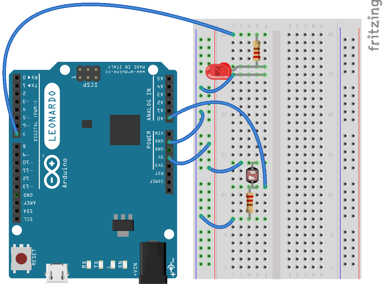
My second challenge for this set of experimentations was to use the original values that were read in above, and apply them to an LED in order to turn the LED on and off at certain light intensities. To do this I simply added an LED to the series and another resistor after the LED which was then connected back to output pin 7. I used the initial value taken from the LDR and set a threshold on this value using if statements. If the output of the LDR got too low, then the LED would be switch on, and if it was above this value it would remain off. This is what I assume to be a very arbitrary example of how automatic street lights work. If the light intensity of the surrounding environment is too low, then the street light will be switched on!
                        // Defining the pin for the LED.
                        const int pin_1 = 7;
                        // Setting initial bool value to True.
                        boolean x = true;

                        // Setting serial port for communication from board to computer.
                        void setup() {
                            Serial.begin(9600);
                            pinMode(pin_1, OUTPUT);
                        }

                        void loop() {
                            // Setting var equal to the output of the LDR.
                            int c = analogRead(A0);
                            Serial.write(int(c));
                            delay(500);
                            // If the LDR is lower than 300, turn LED on.
                            if (c < 300 && x == true) {
                                digitalWrite(7, HIGH);
                                x = false;
                                delay(1000);
                            // Else if the LDR value is higher than 300, turn LED off.
                            } else if (c > 300 && x == false) {
                                digitalWrite(7, LOW);
                                x = true;
                                delay(1000);
                            }
                        }
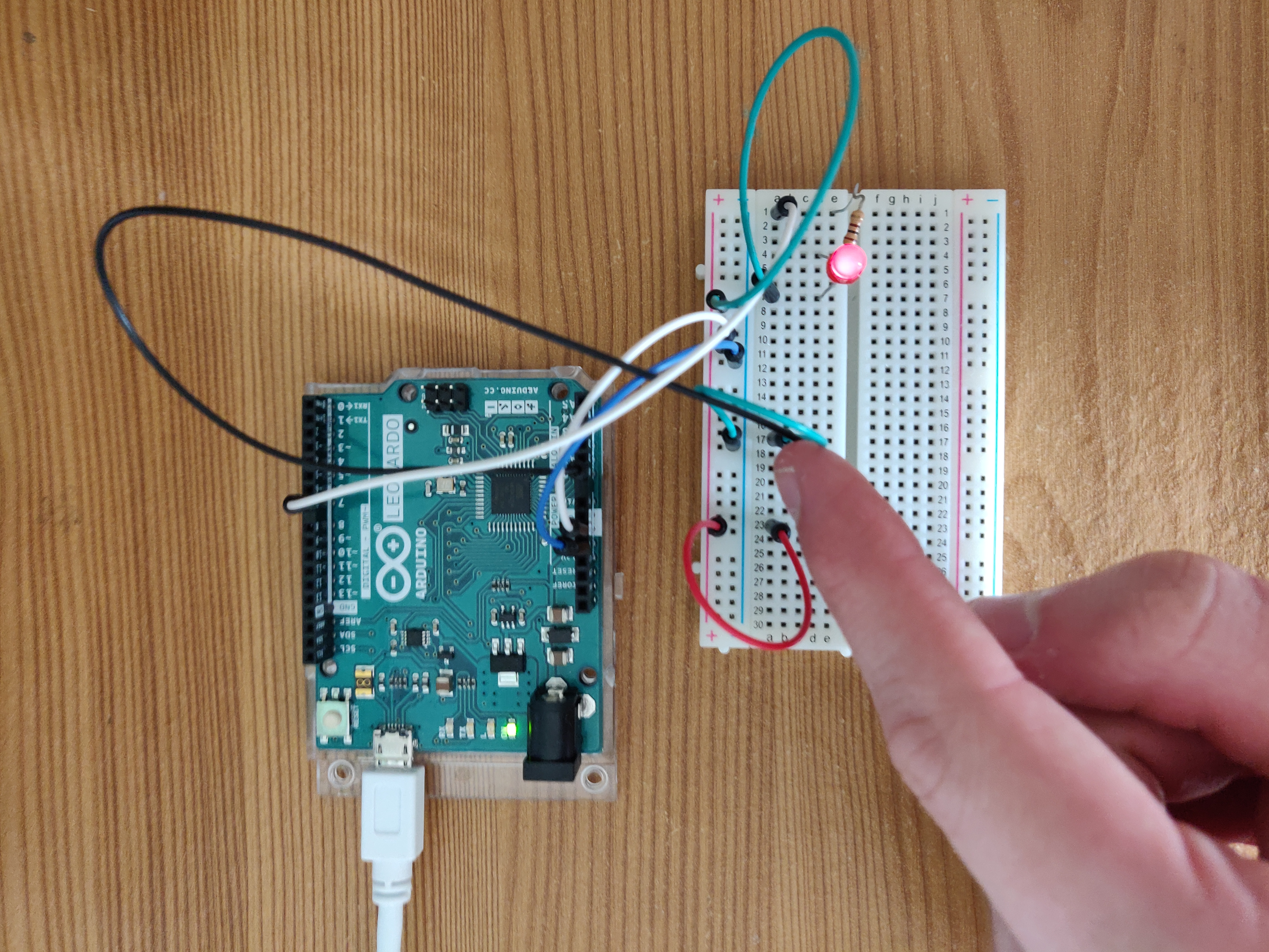
In the picture above the LDR is covered and therefore the LED is turned on. In the picture below, the opposite is true and because the LDR is receiving light, the LED is turned off!
Conclusion...
This set of simple experiments gave me a very basic insight into how Arduinos can be used to gather information and interact with the environment. With a very simple circuit it was possible for me to create something which gathers appropriate data, can convert this data into something useable, and act upon this data! While these experiments are very basic, it does definitely give a further idea of the potential power Arduino’s have when combined with the appropriate software and components!
References...
Khatri, P. (2018). Arduino Light Sensor Circuit using LDR. [online] Circuitdigest.com. Available at: https://circuitdigest.com/microcontroller-projects/arduino-light-sensor-using-ldr/ [Accessed 17 April 2019].
Mirza, K. (2019). Arduino LDR Sensor Sensor Simulation in Proteus - projectiot123 Technology Information Website worldwide. [online] projectiot123 Technology Information Website worldwide. Available at: https://projectiot123.com/2019/03/18/arduino-ldr-sensor-sensor-simulation-in-proteus/ [Accessed 16 Apr. 2019].