Arduino Week 4 - Introduction to Servos
Introducing Servos and Keyboard Interaction!
Introduction...
A servo, short for servomechanism, is a device that uses negative feedback to correct the action of a mechanism. The term does not describe a specific device as such, but it encompmassess a number of devices which perform a specific function or task (Servo Control Facts, n.d.). The most popular applications of servos are in position control and speed control, examples of which include satellite tracking antennas, automatic navigation systems, hard disk drives, and remote controlled vehicles to name but a few! For the purposes of this experiment I was using a SG90 micro servo motor. Servos of this type are controlled by sending an electrical pulse of variable width, or pulse width modulation (PWM), through the control wire. They have a movement range of 180°, or 90° in either direction and are very energy efficient, which makes these micro servo motors perfect for use in projects such as remote controlled cars and robots! They operate by sensing a pulse which is sent to the servo motor by the circuit. This pulse will have a minimum value, a maximum value, and a repetition rate. As stated by Jameco Electronics (n.d.); ‘the servo motor expects to see a pulse every 20 milliseconds (ms) and the length of the pulse will determine how far the motor turns. For example, a 1.5ms pulse will make the motor turn to the 90° position. Shorter than 1.5ms moves it in the counterclockwise direction toward the 0° position, and any longer than 1.5ms will turn the servo in a clockwise direction toward the 180° position’.
Components Needed...
- Arduino.
- Breadboard.
- Jumper Wires.
- Micro Servo Motor.
Simple Servo Interaction...
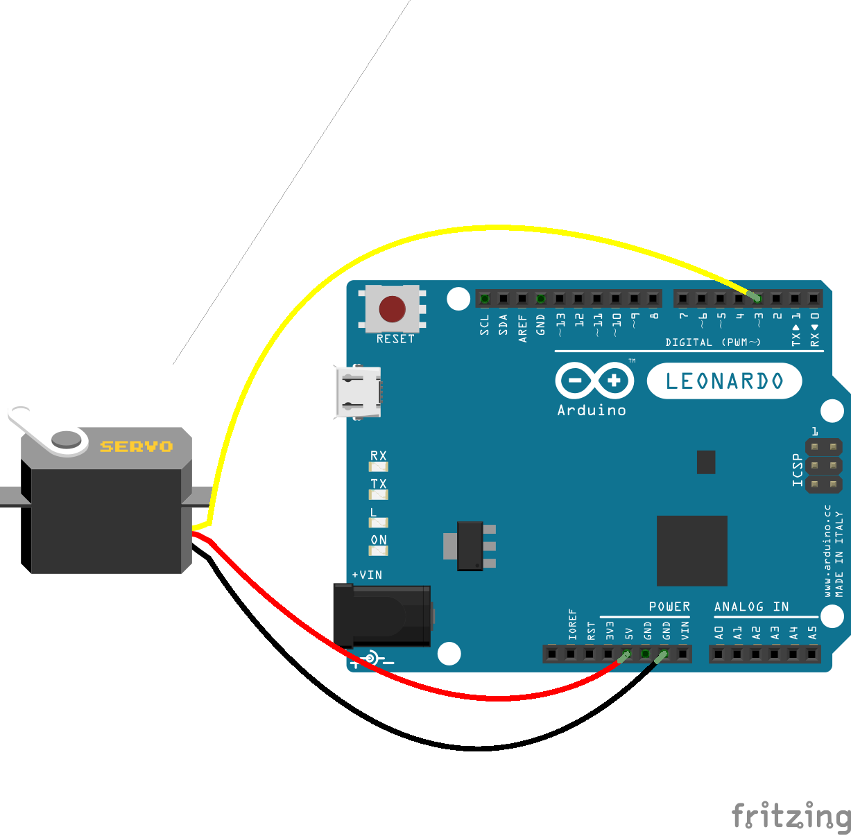
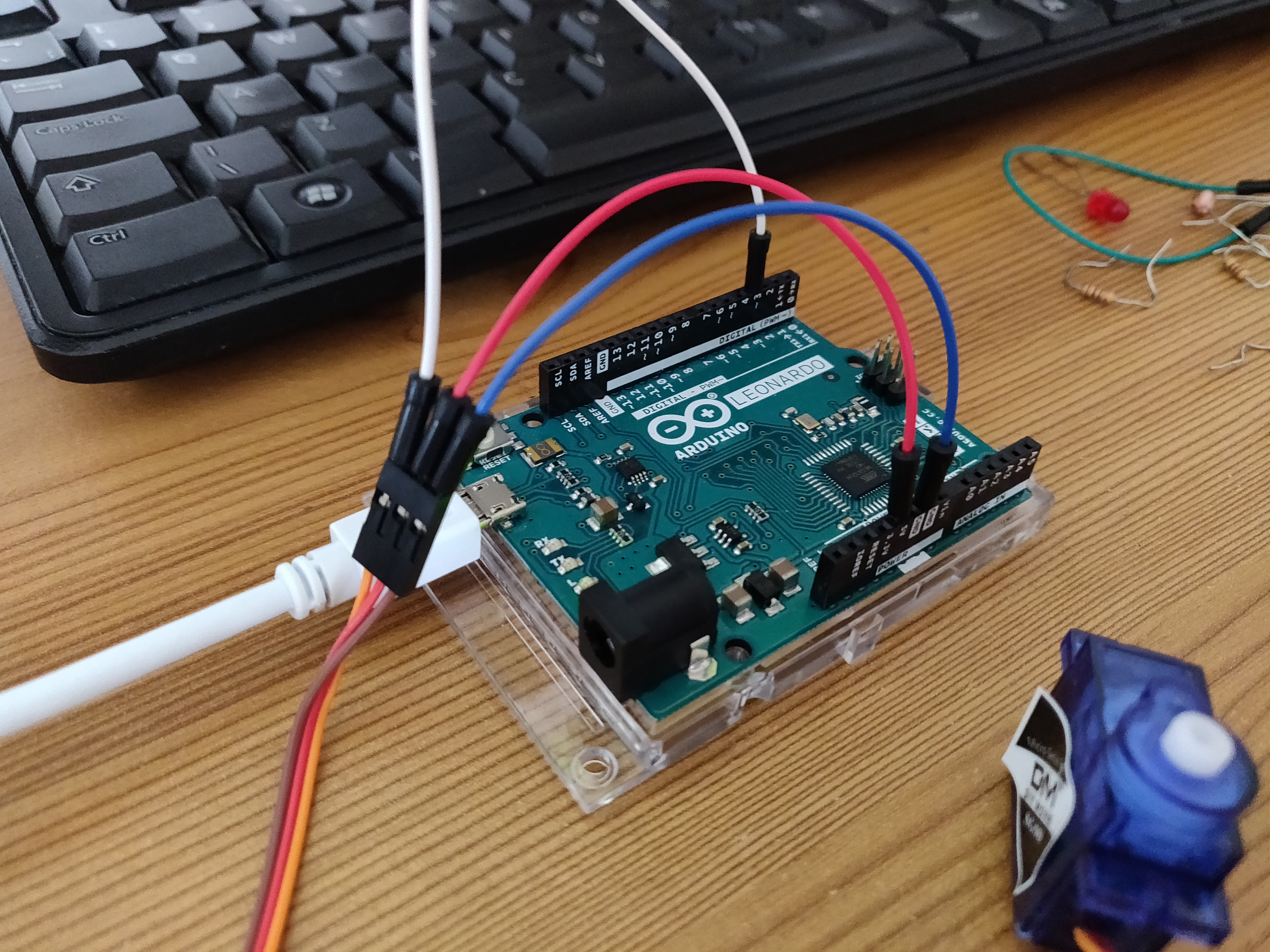
The first step in experimenting with the servo involved me simply getting it to turn! I didn’t have much of an idea of where to start with this, so I followed a tutorial by a user named corenlam on instructables. The circuit for this first experiment was extremely simple, and probably was the simplest circuit so far, as it didn’t involve any use of the breadboard or any other components! Due to the servo Having everything built in, such as the motor and feedback circuit, it means all that is required is a power line, a ground line, and a connection to the control pin on the arduino. To make things even simpler, the large majority of these micro servos come with a female connector, meaning all we need to do is connect three jumper wires from the Arduino to this female connector. The darkest wire from the servo is usually the ground, in my case it was a brown wire. The red wire is the 5V wire, which should be connected to the 5V on the arduino and finally the remaining wire will be connected to a control pin of your choice on the Arduino, in my case I chose the same as the tutorial I was following which was pin 3!
The code was slightly more complex than in previous experiments, mainly due to the fact it involved the use of an external library, but it was nothing too complicated! I included the Servo.h header file in order to gain access to the Servo object, which is necessary to use the servo with the Arduino. A servo object is then instantiated, being named Servo1 in this case. For servos the .write() command is used to specify which angle you want it to turn to between 0° and 180°; 0° being the far right, 90° being the middle and 180° being the far left, depending on which way you are looking at the device of course! There were also a few delays placed in the code in between each interaction with the servo, this was simply so I could observe how the servo moved depending on what value was applied to the .write() function.
                        // Include the Servo library by calling to the Servo header file.
                        #include
                        // Specify pin that the servo is plugged into on the arduino.
                        int servoPin = 3;
                        // Create servo object.
                        Servo Servo1;

                        void setup() {
                            // 'Attach' the servo to the pin number on the arduino as specified above.
                            Servo1.attach(servoPin);
                        }

                        void loop() {
                            // Make the servo go to 0 degrees and delay for 1 second. (1000 ms).
                            Servo1.write(0);
                            delay(1000);
                            // Make the servo go to 90 degrees and delay.
                            Servo1.write(90);
                            delay(1000);
                            // Make the servo go to 180 degrees and delay.
                            Servo1.write(180);
                            delay(1000);
                        }
Simple Keyboard Interaction with Servo...
To take the simple servo experiment a bit further I wanted to try and interact with the servo with the keyboard, much like I had turned the LED on and off with the keyboard in a previous experiment. My initial idea was to use the arrow keys or the ‘A’ and ‘D’ keys as input in order to turn the servo in different directions, much like how I imagine remote controlled vehicles to work. To execute this, I used the same circuit layout as above as no other components were needed. I also used the same code as a base of the experiment as well. All that was needed was to initialise serial communication, check for incoming data, and execute a command based on the users input. I opted to use W, A, and D keys to mimic what a lot of online games use for input. I first initialised serial communication using the Serial.begin(9600) function in setup(). In loop() I wrote a series of nested if statements, the first of which is simply to check if there is any data incoming, and if there is, will go on the check the following statements. The next set of statements check whether the W, A, or S keys have been pressed; if the W key is pressed, the servo will go to its default straight position with Servo1.write(90). If the A or D keys are pressed, then the servo will go left or right, with Servo1.write(180) or Servo1.write(0), correspondingly.
                        // Include the Servo library by calling to the Servo header file.
                        #include
                        // Specify pin that the servo is plugged into on the arduino.
                        int servoPin = 3;
                        // Create servo object.
                        Servo Servo1;

                        byte incomingByte;

                        void setup() {
                            // Initialise serial communication.
                            Serial.begin(9600);
                            // 'Attach' the servo to the pin number on the arduino as specified above.
                            Servo1.attach(servoPin);
                        }

                        void loop() {
                            // Check to see if there is incoming serial data.
                            if (Serial.available() > 0) {
                                incomingByte = Serial.read();
                                if (incomingByte == 'W' || incomingByte == 'w') {
                                    Serial.write("Straight.\n");
                                    Servo1.write(90);
                                } else if (incomingByte == 'A' || incomingByte == 'a') {
                                    Serial.write("Left.\n");
                                    Servo1.write(180);
                                } else if (incomingByte == 'D' || incomingByte == 'd') {
                                    Serial.write("Right.\n");
                                    Servo1.write(0);
                                }
                            }
                        }
Conclusion...
Overall, these were definitely some exciting experiments and definitely gave me more of an idea of what I could pursue for a potential final project or artefact. Getting input from the keyboard is also an exciting prospect, as interacting with any component on the arduino is always a lot more fun when you can specify what it does rather than just relying on a predetermined set of instructions! For future experimentation with the servo, I would be keen to see if I could implement a solution that allows me to operate it remotely, potentially through the use of a bluetooth module, or maybe through connecting it to a Raspberry Pi that is also connected to a local network.
References...
Instructables.com. (2016). [online] Available at: https://www.instructables.com/id/Arduino-Servo-Motors/ [Accessed 13 Mar. 2019].
Jameco.com. (n.d.). How Servo Motors Work | Servo Motor Controllers. [online] Available at: https://www.jameco.com/jameco/workshop/howitworks/how-servo-motors-work.html [Accessed 12 Mar. 2019].
Servo Control Facts. (n.d.). [ebook] Baldor Electric Company. Available at: https://www.baldor.com/Shared/manuals/1205-394.pdf [Accessed 8 Mar. 2019].